One module. One machine. Every signal that matters.
AndonTap is a 26.4 mm wide DIN-rail module that watches one machine. It reads the stack light, up to four 24 V machine signals and two clip-on current transformers, works out the machine state, counts and run times on board, and serves them over Ethernet.
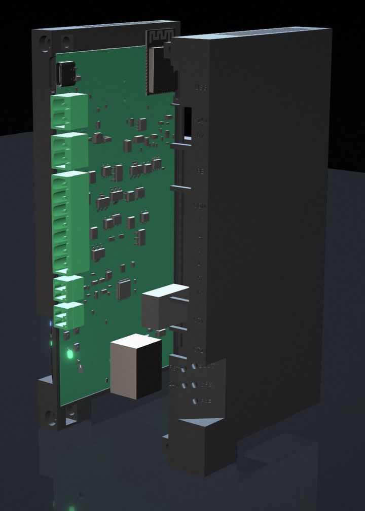
Every terminal and indicator on the front
Pluggable screw terminals, top to bottom as mounted on a horizontal rail. The three plugs have different pin counts, so power, the 120 V group and the 24 V group cannot be swapped by accident.
| Connection | What it is |
|---|---|
| Power | +24V · 0V · PE3-pin pluggable, 5.08 mm. Optional when the unit runs on PoE. |
| Inputs 1-4 | COM-A · IN1-IN45-pin pluggable, 5.08 mm. 24 VDC or 120 VAC, either polarity on DC, behind an internal isolation barrier. |
| Inputs 5-8 | 24V OUT · 0V · COM-B · IN5-IN8 Firmware planned7-pin pluggable, 3.5 mm. 24 VDC only, sinking or sourcing. |
| CT1 · CT2 | 2-pin pluggable, 3.5 mm each333 mV or 1 V AC split-core CTs. |
| RJ45 | 10/100 Ethernet with PoEBottom end wall, so the cable drops into the wire duct. |
| USB-C | Setup console, firmware loading, bench powerNot meant as a permanent connection. |
| SMA | LoRaWAN antenna PlannedTop end wall, LoRaWAN builds only. A closed knock-out otherwise. |
| Indicators | 24V · PoE · STATUS · BT · FAULTFive LEDs through light pipes, plus CFG (Bluetooth on for 10 min), RST and BOOT. |
Two input groups, two CTs
A stack light is often 120 VAC; door switches and M-code relays are usually 24 VDC. V6 keeps them on separate plugs with separate commons, so the 24 V group stays low-voltage.
Stack light, 24 VDC or 120 VAC
Each input runs through a bridge rectifier and a 2 mA constant-current stage into an optocoupler, so the same circuit takes 24 VDC or 120 VAC 50/60 Hz with no jumpers.
- Factory setting: IN1 red, IN2 amber, IN3 green; IN4 for a fourth tier, a part counter or a signal.
- Steady and flashing lamps are told apart; a 120 VAC input is held on through the zero crossings.
- About 2 mA per input: wire it in parallel with the lamps.
- One voltage per group. All four share COM-A: all 120 VAC or all 24 VDC from one circuit.
Machine signals, 24 VDC Firmware planned
Door switch, feed hold, part count, lube, air or coolant switches, M-code relays, operator call. Bidirectional optocouplers make them sinking or sourcing, like a PLC input card.
- COM-B to 0V for PNP sensors and dry contacts; COM-B to +24V for NPN sensors.
- ON at about 8 V (design value), so 12 V machine signals switch with margin.
- On-board 24V OUT (0.1 A, fused) feeds dry contacts, even on PoE alone.
- The hardware is on every V6 unit. Firmware 1.5 does not read these inputs yet; wire them now and the data appears after the update.
Spindle and auxiliary current
Standard voltage-output split-core CTs, 333 mV or 1 V AC at full scale, rated anywhere from 1 to 5000 A. Read as true RMS with a 16-bit converter.
- CT1 watches the spindle: stopped, turning or cutting, with 10 % hysteresis.
- CT2 watches coolant, a conveyor, hydraulics, main power or a second spindle.
- Clamp around one phase conductor. For small currents, loop it 1-20 times and set the passes.
- Never a 1 A / 5 A current-output CT.
Rules you can read
Up to 8 IF/THEN rules, each with up to 3 conditions on lamp colours, single inputs, spindle level, CT2 and 24 V power. The first rule that matches sets the state; the setup app highlights the one matching right now.
States: 0 Unknown · 1 Off · 2 Idle · 3 Running · 4 Alarm · 5 Setup · 6 Warning · 7 Maintenance. The unit keeps the seconds spent in each state and the time in the current one.
On a PoE-only unit with nothing wired to the power plug, change or delete the "no 24 V = Off" rule in setup, or the machine will always read Off.
| # | Factory rule: if | then |
|---|---|---|
| 1 | No 24 V on the power plug | Off |
| 2 | Red on or flashing | Alarm |
| 3 | Green flashing | Setup |
| 4 | Green on | Running |
| 5 | Amber on or flashing | Warning |
| – | None of the above | Idle |
Built for plant networks
Power
- PoE built into every unit: IEEE 802.3af, Class 0, isolated PoE module.
- 24 VDC on the power plug, with reverse-polarity, fuse and surge protection.
- Both at once is fine: the unit keeps running if either one fails.
- USB-C powers it on the bench for setup.
Network
- A new unit has no IP address and sends nothing: no DHCP requests, no IPv6.
- Static IP by default; DHCP if you want it. Wi-Fi is off.
- Modbus TCP server (port 502) and EtherNet/IP adapter (44818, I/O on UDP 2222).
- Remote-write level: off, basic (default) or full, for what network clients may change.
Setup and updates
- Browser setup app over USB-C or Bluetooth LE; Chrome or Edge, Chrome on Android, Bluefy on iPhone.
- Planned: once a unit has its IP address, open
http://<unit IP>from any PC on the plant network to see the live screens and make changes. The unit serves the app itself; changes need the setup PIN. First-time addressing stays at the unit (USB-C or Bluetooth). - Bluetooth is on only with no IP set or for 10 minutes after a CFG press. Optional setup PIN.
- Network firmware updates, one unit or a whole plant, roll back by themselves if the new version fails. Images are not signed yet.
- Settings and counters are kept over updates.
What you order
| Standard unit | Ethernet with PoE, 8 inputs, 2 CT inputs. Power from PoE or 24 VDC. |
|---|---|
| LoRaWAN option Planned | Adds an on-board RAK3172 LoRaWAN module, a pigtail and an SMA jack in the top end wall. The antenna is sold separately (see accessories). |
| Base kit | The unit, ready to wire. |
| CT bundle | The base kit plus one split-core CT. |
In the box To be confirmed
- AndonTap V6 unit with every mating plug fitted: power, IN1-4, IN5-8, CT1, CT2
- Quick Start Guide and a write-on input label sheet
- DIN-rail end stop
- CT bundle only: one split-core CT
Not included: USB-C cable, Ethernet cable, ferrules. LoRaWAN units: antenna sold separately, required before enabling LoRaWAN.
Get the details in writing
Every number on one page in the datasheet, or the full install and setup instructions in the manual.